Tuesday, April 30, 2013
2010 Hyundai Elantra Owners Manual
Friday, April 26, 2013
2012 Honda Civic Coupe Owners Manual
 |
| Google Images |
Wednesday, April 10, 2013
Construction Working of Differential Assembly


Friday, April 5, 2013
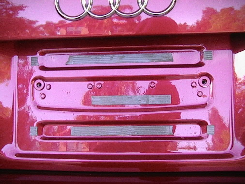
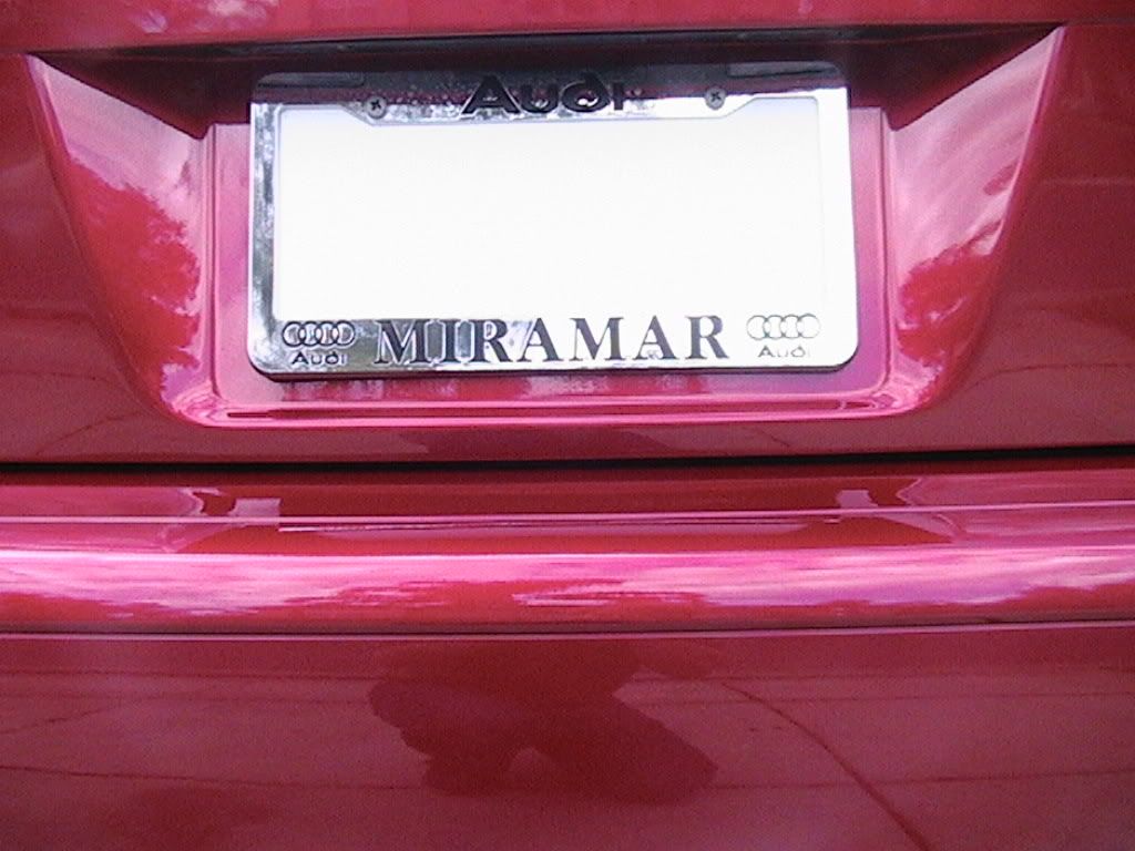
Audi A3 Trim License Plate Backing Plate
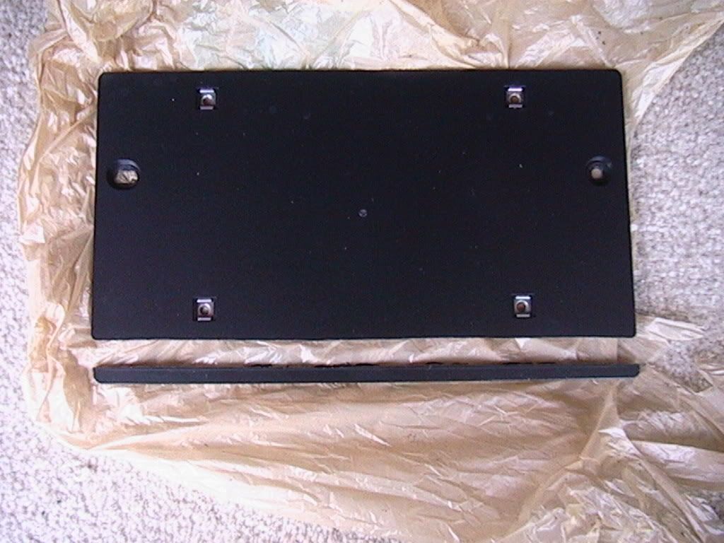
The first step is to mark where the license plate frame hits the bottom of the backing plate. I didnt have a pen that would mark the black plastic so I took a razor blade cutter and scratched a line in the backing plate. I scratched from one side to the middle and then from the other side and to the middle so there was no risk of slipping and cutting into the paint. (Well, very little risk anyway. You may wish to find a marking pen that will work.)
Now remove the license plate frame. Then remove the two bolts holding the backing plate to the car. I dont know what kind of tool is supposed to take them out but I found that a 5/32" allen wrench did the trick.
Now youll find that the backing plate is stuck rather firmly to the car. Dont worry, its just some double-stick foam tape. Get your fingernails under a lower corner and pull the backing plate away from the car. Apply steady pressure and let the foam tape slowly give. DO NOT just yank it off! Just keep pulling until youve got the corner an inch or so away from the car.
The foam tape should stick to the car in some places and to the backing plate in others and just stretch between the two. Instead of just pulling until it breaks, carefully snip the tape with a pair of scissors wherever it is stretching between the car and the backing plate. The result looks like this:
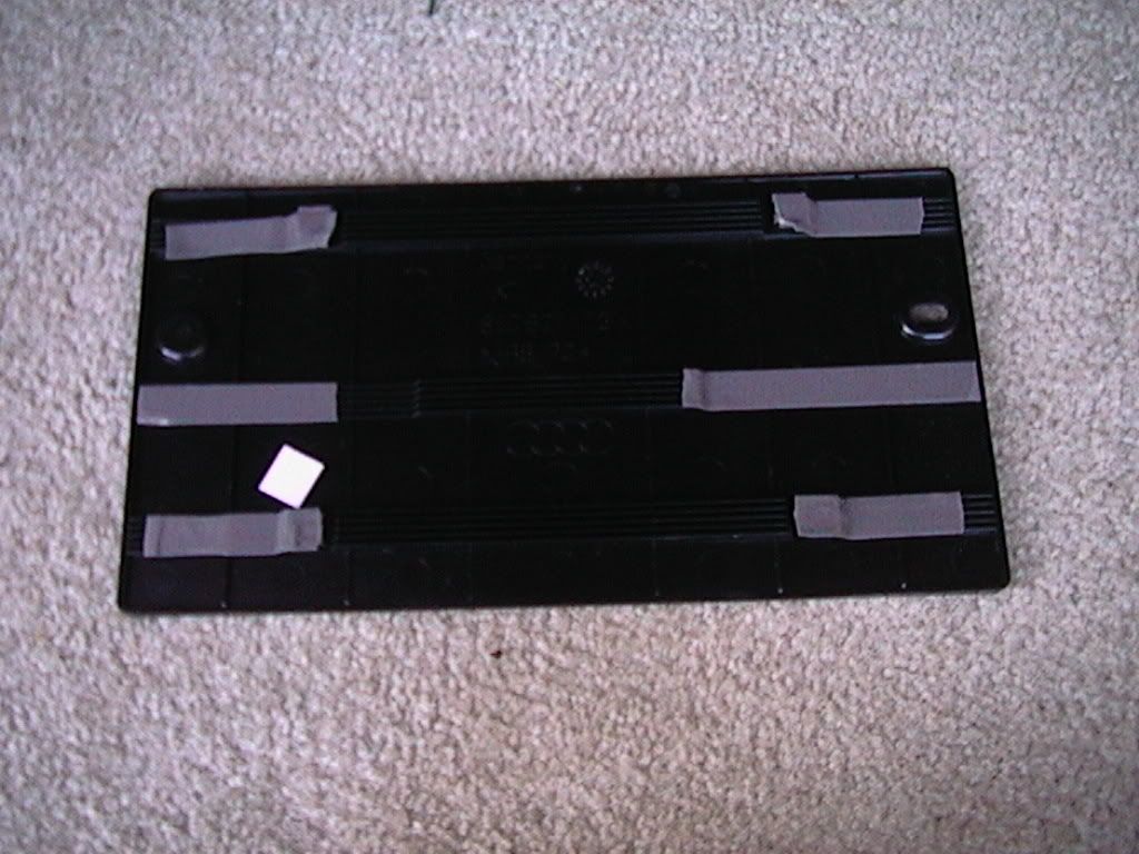
The tape stretches a bit and you do not want there to be overlap of the tape when you put it back together so cut off a little from the ends of the tape. Resulting in this:
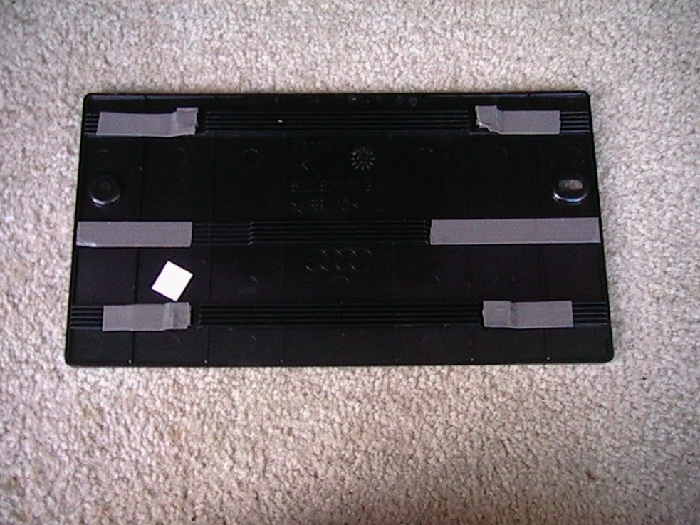
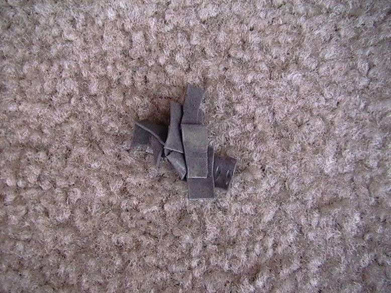
That last one is the stack of little pieces of foam tape that I cut off.
If youve got some of the foam tape for body molding you can just remove all the tape piece and replace it with new. It comes off fairly easily. A lot easier than the stuff holding the badges on. I probably would have done this except I had just used the last of my tape last month when a body molding piece peeled off my Jetta.
Once removed, if not completely removing the foam tape you should protect it from getting any dirt or plastic shavings on it. I used a plastic grocery sack and just stuck it to the tape.
Now your ready to cut. To cut it you can use a dremel tool, jig saw, hack saw, or whatever else youve got around that could work. I even considered a pair of tin snips but was afraid I would crack the plastic. Anyway, since I dont have a dremel tool and my jig saw would require an extension cord, I opted for using a hack saw with a soft-metal blade (larger teeth). The jig saw would have been better but all my extension cords were being used for Christmas lights. 
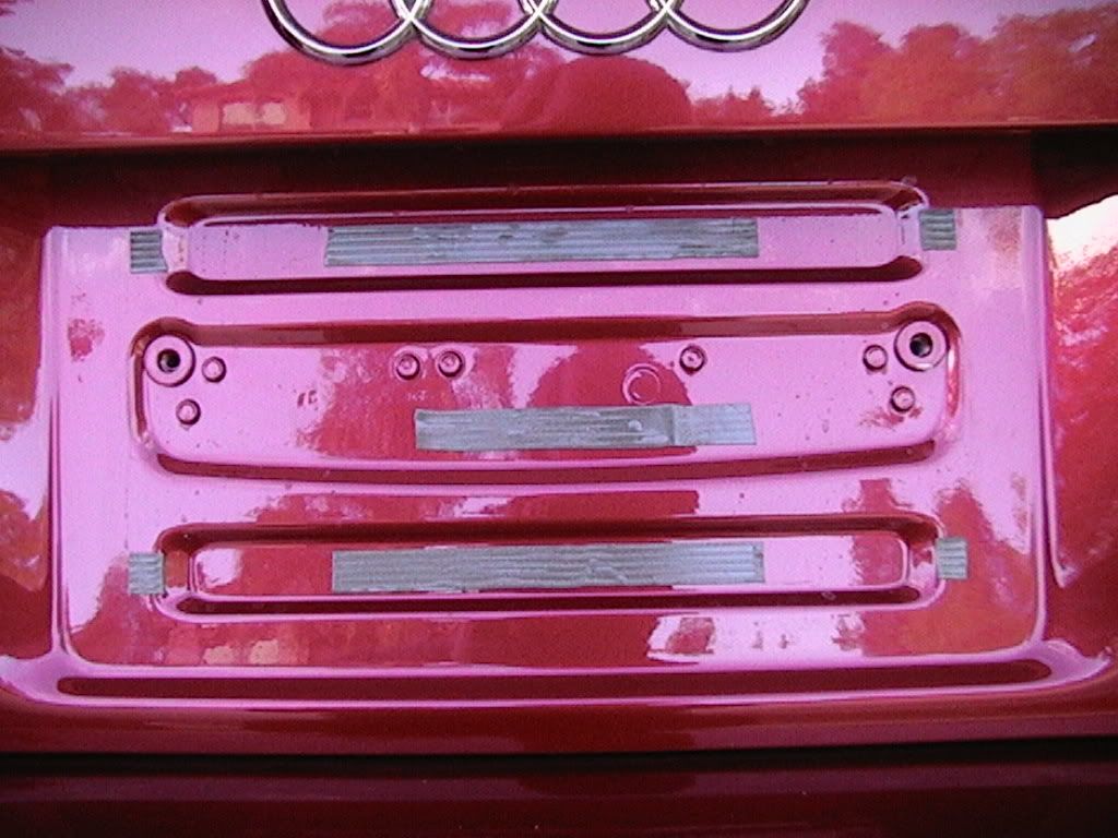
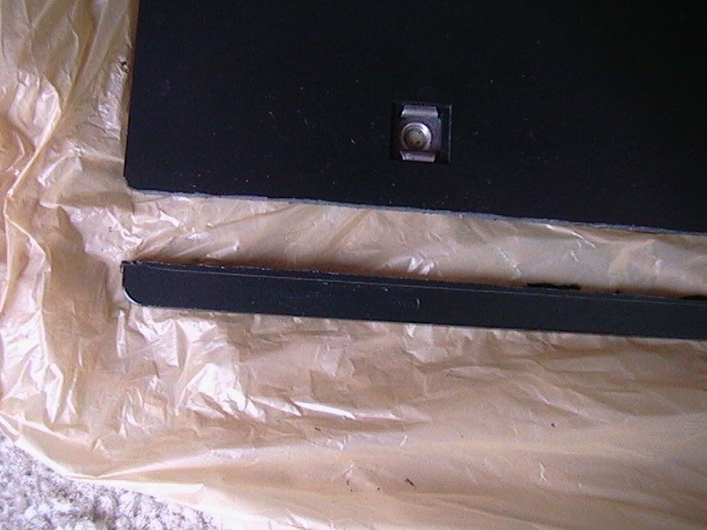
I started the cut about 1/4" above the line scratched on the bottom of the backing plate. I think that should be adequate for any size plate frame. I will be replacing the dealer frame eventually. After cutting, trim the the edges with a razor blade cutter to remove any sharp edges and loose pieces. Heres the result:
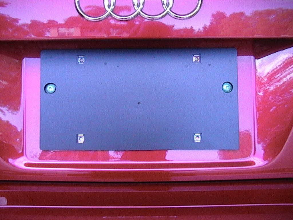
Just put the backing plate back in place, attach with two bolts, and attach the license plate and frame. All done! Heres the end result:
Thursday, April 4, 2013
Audi A4 PhatNoise Installation
Background:
For those that dont know about the Phatbox... its basically a purpose built digital audio player supporting MP3s, WAV, WMA, etc. The Phatbox hardware runs a slimmed down Linux kernel and it interfaces directly with the Audi factory CD-Changer wiring through a custom Blitzsafe adapter. A 20GB laptop hard drive encased in a Digital Media Storage cartridge provides the storage space. A USB cradle allows you to sync MP3s between the Phatbox and your home collection using the inlcuded software.
The Blitz adapter basically fools the headunit into thinking a CD-Changer is connected while passing control inputs from the headunit back to the Phatbox. The operation of the unit is pretty simple... the disc selection buttons (1-6) on the Symphony headunit activate different modes on the headunit, allowing you to search by artist, album, playlist, etc.
Heres a pic of the whole system as I received it from Phatnoise.

The Phatbox uses the pre-existing CD-Changer wiring. The logical place to install the Phatbox was in the CD-Changer rack. The CD-Changer connector is wrapped up in the grey foam wrapping behind the rack.

Space around the rack is pretty tight so its best to remove the whole assembly to work on it. The rack is secured by five 7-mm hex head screws. Unfortunately these five screws are hidden behind the trunk liner, and you cant really get tools back there without at least partially removing the liner on the drivers side. This required removing the interior rear bumper fascia so that the liner could be removed, freeing up access to the rack. Its not hard, but it is time consuming. I was able to use a power screw driver and a flexible extension to remove the screws once I unclipped the back half of the liner. Once you have the rack free you have to carefully turn it over until you can get to the small box that is attached to the bottom of the rack. I dont know what this small unit does but it is held on the rack by three small phillips head screws.

Once youve got the rack free you can wiggle it out of the opening in the partially detached liner. Heres a shot of the trunk after I removed the rack. Note that the liner is partially loose and the carpet in the trunk floor is pulled back.
I used some industrial strength Velcro (the stuff you see on David Letterman) to secure the Phatbox in the rack. Initially I was going to drill holes and use the included self-tapping screws to secure the box, but the geometry of the rack doesnt allow you to drill the necessary holes, and besides, this Velcro is good stuff, it sticks like superglue and the Phatbox doesnt budge at all.
After reattaching the black box to the bottom of the rack I positioned the rack back in its spot in the trunk.
I connected the necessary adapters before securing the rack in the trunk with the screws (again using the handy powered screwdriver and flexible extension). The adapter was secured in the lowest portion of the rack with some leftover Velcro.
The slightly concave shape of the toolbox door easily clears the DMS cartridge sticking out of the front of the Phatbox. Theres also just enough room behind the Phatbox for the cables to run without binding. Incidentally there is a *ton* of space below the rack... you could install all sorts of goodies there...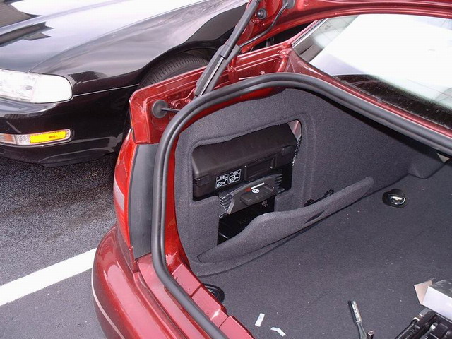
After I cleaned up my mess and restored the trunk liner you end up with a perfectly stealth installation. Just like I wanted. The cars sixth chakra is glowing in approval.
Wednesday, April 3, 2013
2010 Subaru Outback Owners Manual

Before you operate your vehicle, carefully read this manual. To protect yourself and extend the service life of your vehicle, follow the instructions in this manual. Failure to observe these instructions may result in serious injury and damage to your vehicle.
Table of content 2010 Subaru Outback Owners Manual
- Seat, seatbelt and SRS airbags
- Keys and doors
- Instruments and controls
- Climate control
- Audio
- Interior equipment
- Starting and operating
- Driving tips
- In case of emergency
- Appearance care
- Maintenance and service
- Specifications
- Consumer information and Reporting safety defects
- Index
Tuesday, April 2, 2013
Audi A4 Installing a CD Changer Under Rear Deck
The reason I installed the CD-changer underneath the rear deck was because I didnt want to take up any valuable storage space, and I wanted to keep it out of harms way from items moving around in the trunk.
The CD-changer I used was the Panasonic model DP-801. However, these installation instructions should work with the DP-601 or the Audi changer.
The Panasonic DP-801 is an 8 CD changer which I ordered from autotoys.com. Total was $235 which included the adapter that fits into the factory connector in the trunk. I went with this model because it is cheaper that the Audi changer, and it holds 8 CDs instead of 6. To access the 7th and 8th CDs, you can use the left and right arrow keys to scroll through the CDs. Two drawbacks to using the this changer are that you lose the random function, and it is not covered under the three-year warranty like the Audi changer is.
Please read disclaimer before you perform this installation.
| First you need to find the connector located in the trunk, on the left hand side behind the trunk liner. Use a flat-head screwdriver to pop off the the two plastic connectors behind the rear-left tail light. Carefully work the top of the trunk liner out enough that you can get your arm behind there. Feel around until you find the round connector. The top of it should be covered with a piece of foam. When you find it, it may be fastened with wire-ties to another bundle of wires. You will need to clip these ties with scissors or wire-cutters to let out enough slack. BE CAREFUL not to cut any other wires! As you can see from the picture, you will find the 25 pin connector back there also, which is used for the cellular phone transceiver. | 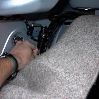 |
| Bring the wire to the front of the liner close to the rear seats. As you can see from the picture, the front of the rear deck has a large hollow support with circular holes underneath. Feed the connector through the first hole, and let it dangle out one of the next ones (youll see why later). Then push the liner back in place, and re-attach the plastic fasteners. | 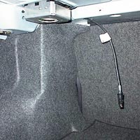 |
| Next, you need to remove the rear deck. First pull out the connector to the rear brake light. | 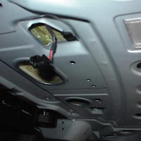 |
| Now you need to get on your back inside the trunk. The rear deck is held in by three white fasteners at the front of the deck. There is one in the middle and one on each side. You can see them through the circular holes. I pushed them in using a flat-head screwdriver and a little persuasion, but you can also use a nail set and a hammer (or something like that). The fastener in the middle isnt exposed, so I had to pry it up from the side with the flat-head. | 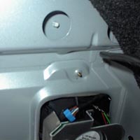 |
| Once they are all popped up, from the back seat you should be able to lift the deck up can carefully pull it towards you. The seat belts pass through the rear deck, so they will be let out. | 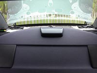 |
| You need to set your changer to be installed in the horizontal position. On the Panasonic changer, I believe there is a small adjustment on the side. The mounting hardware included with the changer has two silver brackets with threaded screws attached, and two black brackets which attach to the changer. The silver brackets are placed upside-down with the screws going through the deck, and the changer is bolted on to those screws from underneath. | 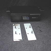 |
| Here is a picture taken through the rear window. There are two large openings in center of the deck which are perfect for putting the brackets through. I have placed the brackets in those holes for this photo. However, I didnt want the changer to be in the center of the deck. I thought it would look better and be more out of the way if it was offset to the side. This required some new holes, so I drilled three holes indicated by the red arrows. The fourth hole was already there. (no drilling is required if you use the openings in the center.) Also, there is no specific reason why I chose the right side. The left should work just as easily. I put the double-sided tape underneath the brackets so they dont slide. You probably dont need it, but it gave me a better piece of mind. | 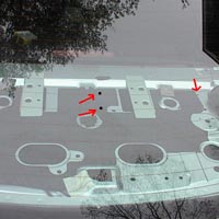 |
| This picture is an example of how the changer attaches to the brackets from underneath. You really need to get on your back in the trunk to screw it in. Tighten the nuts, but not too much. The silver brackets on the top of the deck form sort of a bridge over the holes, so if you keep tightening them they will keep bending. You can sort of see this from the previous picture. I tightened the nuts just enough to make a slight bend so I knew it was taught. |  |
| Now attach the supplied adapter to the connector. The two connectors didnt click together. It felt like they could come apart easily, so I wrapped them up in electrical tape to hold them together. Then you can feed the wire down the hollow track, and out the hole closest to your changer. | 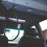 |
| For the last step, I drilled a small hole for the ground wire and attached it to a sheet metal screw. I think there was a couple screws I could have used on the speaker, but I wanted the install to be as clean as possible. | 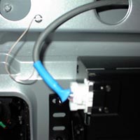 |
| Now put the rear deck back in place. When the white fasteners are lined up with the holes, give the front of each a good whack with your fist to pop them back in place (you can hear them pop back in, so youll know when). Dont forget to re-connect the brake light! Throw in a few CDs and go for a cruise! | 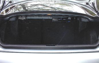 |
Disclaimer:
This installation has been proven to work with the owners vehicle. He cannot be held responsible for any damage to the vehicle or CD changer, or any personal injury. Do not perform this installation if you are not totally confident that you can perform it without any damage.
Monday, April 1, 2013
Audi A8 Flushing the Power Steering Hydraulic System
Tools and Materials Required
- 2 Liters of hydraulic fluid, part number G 002 000 (about $20/liter)
- (2) 1" hose clamp for power steering hydraulic lines
- Small bucket for draining fluid
- Needle nose pliers and screwdriver
- Golf tee
- Brake cleaner, rags and compressed air
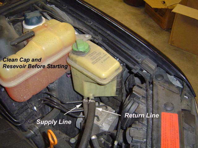
Remove the hydraulic reservoir by lifting it out of its cradle. The supply line comes from the transmission cooler in the radiator, it is the lower, smaller hose. The return line to the pump is the higher, larger line.
Wipe down the reservoir. Remove the factory clamp on the return line by prying it with some needle nose pliers. Place a bucket under the reservoir, take off line and drain reservoir into bucket.
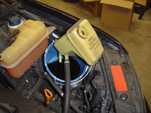
Drain reservoir after removing lower, supply line.
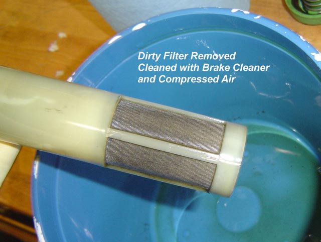
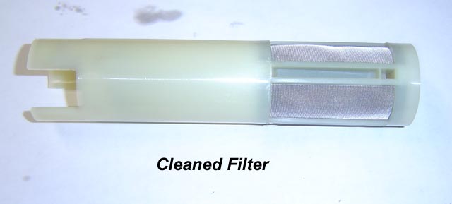
Remove the filter from the reservoir. Clean it to remove any foreign material. I used brake cleaner over the bucket that I used to drain the fluid into. I then sprayed it with compressed air to clean and dry it.
Flushing the System
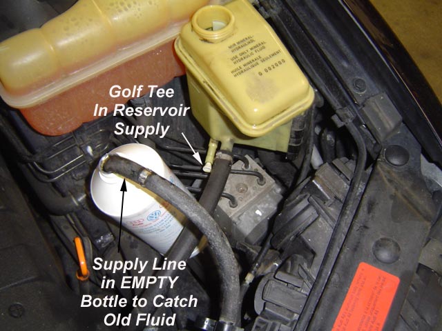
One the reservoir is empty and the filter cleaned, place a golf tee in the supply line of the reservoir. This will allow you to fill the reservoir with fresh fluid and not have it leak out.
Fill the reservoir with fresh hydraulic fluid. It will take the entire liter of fluid. Place the supply line into the empty container and ensure it wont tip over.

IMPORTANT: Do not run the car for more than 4 seconds in the following step so that the reservoir will not go dry.
Start the engine and count 4 seconds. Turn off the engine. This pumps clean fluid from the reservoir to the pump, through the system. The old fluid is collected in the empty container. 4 seconds of engine operation will pump about 2/3 liter through the system.
Empty the collection bottle. Place supply line back in it.
Fill the reservoir again. Start the engine and run for 4 seconds. Secure engine. If you pour some of the fluid out of the collection bottle, you will see that it is clean. This completes the flush.
NOTE: If you run the car more than 4 seconds each time, you could consume more than 2 liters of fluid. If this happens and the second run through the system produced clean fluid in the collection bottle, use it to top off the system.
When complete, install the supply line with a new hose clamp, replace the return line with a hose clamp if youd like. If its leaking, please do.
Place the reservoir back into the cradle and top the fluid just below "full" because the fluid is ambient temperature and will expand as it heats up to normal operating temperature.
Notes on Doing a C5 A6 from Jon Cole:
On the 01 A6 you have to unbolt the reservoir from the side of the engine compartment, no big deal at all. The bottom of the reservoir rests in a padded press fitting, you have to lift it out firmly but gently.
The supply side line seems much shorter than on the A8, too short to get up and into an empty bottle, so I put a piece of extension hose on it (not sure of size, I use it for my shop vac and coolant (but its clean). One advantage was that the clear extension hose looped up high enough before going into the bottle that I could see what was pumping into it, both as to amount and color.
You also have to remove a plastic housing that holds about 5-6 electrical connectors, I moved it up out of the way and held it there with a velcro strap around it to support it, and reinstalled it.
The reservoir on the A6 holds less than the A8, apparently; refilling the reservoir uses maybe 1/3 to less than 1/2 liter. So I cranked for only 1-2 seconds at a time rather than 4 - that emptied the reservoir.
Upon refilling I let it bleed some air out (you could see slow bubbling and a tap or 3 with a screwdriver helped it along) before doing the next pump sequence. Did about 4 2 second pumps and that pumped about 1.5 liters, at which point it was running nice & green. A 1" hose clamp will work on the supply line but a smaller one fits better.